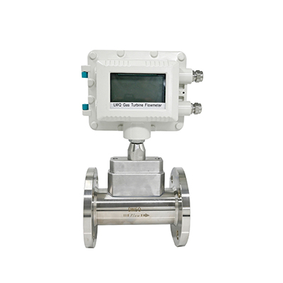

LWLWG series gas turbine flowmeter is mainly used for flow measurement of natural gas, air, nitrogen and other medium fluids in industrial pipelines. When measuring the working volume flow, it is almost unaffected by fluid density, pressure, temperature, viscosity and other parameters. It has high reliability and low maintenance, and can work in the working temperature range of -10℃~+100℃.
1. Product Features
(1) High precision: the accuracy level is 1.0%-1.5%;
(2) Good repeatability: Generally, it can reach 0.05% to 0.2%. Due to its good repeatability, it can achieve extremely high accuracy after calibration or online calibration. Therefore, it is one of the preferred flow meters in trade settlement.
(3) Wide range: Medium and large diameters can generally reach more than 20:1, small diameters are 10:1, and the starting flow rate is also low;
(4) Small pressure loss: generally 0.1-2.5KPa under normal pressure;
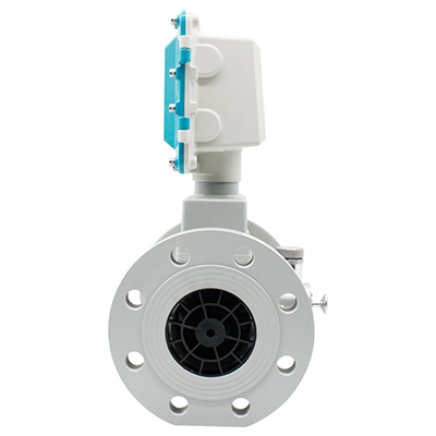
(5) Compact structure, light volume, convenient installation and use, large flow capacity;
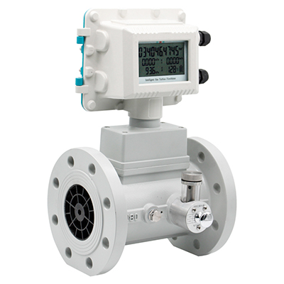
(6) It can adopt a variety of display modes, it can be equipped with only a mechanical counter or only a common flow totalizer, it can also add a temperature and pressure compensator to the mechanical counter, or only carry a temperature and pressure compensator, and it can be powered by lithium batteries for a long time, which is easy to use;
(7) Since pulse frequency signal output is generally adopted, it is suitable for total quantity measurement and connection with computer, has no zero drift and strong anti-interference ability.
2. Industry Application
Natural gas, coal gas, chemical gas, light hydrocarbon gas, nitrogen, compressed air and other low and medium velocity gases.
3. Technical parameters
Instrument caliber and connection method | 25, 40, 50, 80, 100, 150, 200, 250, 300 are connected by flange |
Accuracy level | ±1.5%R; ±1%R |
Range Ratio | 1:10; 1:20; 1:30 |
Display Mode | The wide screen display simultaneously displays instantaneous flow, daily cumulative flow, and total cumulative flow |
Temperature, pressure, time, date, battery level | |
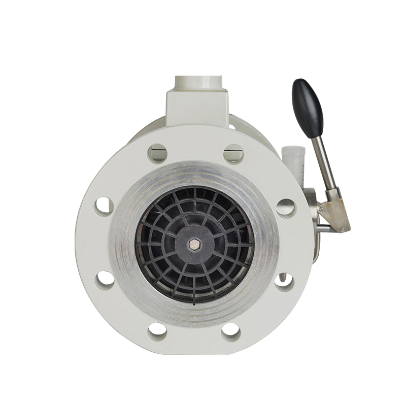
Instrument material | Meter body: 304 stainless steel, cast aluminum; Impeller: anti-corrosion ABS or high-quality aluminum alloy; Display: cast aluminum; Bearings imported from Germany |
Temperature and pressure sensors | built-in |
Temperature of the medium being measured | -10℃~+100℃ |
Environmental conditions | Medium temperature: -10℃~+100℃, relative humidity 5%~90%, atmospheric pressure 86~106KPa |
Communication signal | Three-wire pulse |
Three-wire 4-20mA, RS485 protocol, IC card signal | |
Power supply | Built-in lithium battery; external 24VDC dual power supply |
Transmission distance | ≤1000m |
Signal line interface | Internal thread M20×1.5 |
Protection level | IP65 |
4. Product caliber and flow range comparison table
Specification | Nominal diameter (mm) | Flow range (m3/h) | Starting flow (m3/h) | Pressure resistance (MPa) | Installation form |
DN25 | 25 (1") | 3-30 | 2 | 1.6 | Flange |
DN32 | 32 (1.25") | 5-50 | 3 | 1.6 | Flange |
DN40 | 40 (1.5") | 6-60 | 5 | Flange | |
DN50 | 50 (2") | 10-100 | 7 | 1.6 | Flange |
DN65 | 65 (2.5") | 18-180 | 10 | 1.6 | Flange |
DN80 | 80 (3") | 20-400 | 15 | 1.6 | Flange |
DN100 | 100 (4") | 30-500 | 20 | 1.6 | Flange |
DN125 | 125 (5") | 50-600 | 30 | 1.6 | Flange |
DN150 | 150 (6") | 90-1800 | 40 | 1.6 | Flange |
DN200 | 200 (8") | 150-2500 | 60 | 1.6 | Flange |
DN250 | 250 (10") | 200-4300 | 100 | 1.6 | |
DN300 | 300 (12") | 300-6300 | 200 | 1.6 |
Note: Please order in advance for pressures above 1.6Mpa.
6. Installation instructions and diagrams
(1) Before installation, the pipeline must be purged clean to prevent residual iron filings from affecting the normal operation of the flow meter.
(2) Before installation, when a small airflow is used to blow the turbine, the turbine can rotate flexibly without irregular noise, and the counter rotates normally without intermittent jamming. The flow meter can be installed and used.
(3) When installing the flow meter, a sealing gasket should be added between the flange and the pipe flange.
(4) A filter should be installed before the flow meter. A filter should be installed in places where the air quality is relatively dirty. Before placing an order, the user can place an order with our company at the same time. It is strictly forbidden to directly connect the filter and the flow meter.
(5) Stop valves should be added before and after the flow meter is installed.
(6) There should be no protrusions on the inner diameter of the pipe where the flange is connected.
(7) When installing the flow meter, it is strictly forbidden to perform electric welding directly on its inlet and outlet flanges to avoid burning the internal parts of the flow meter.
(8) The flow meter should be installed in a place that is easy to maintain, free from strong electromagnetic interference, mechanical vibration and heat radiation;
(9) The flow meter should not be used in situations where the flow is frequently interrupted or there is strong pulsating flow or pressure pulsation;
(10) When the flow meter is installed outdoors, there should be a cover on the top to prevent rainwater from seeping in and exposure to the sun from affecting the service life of the flow meter;
(11) The flow meter can be installed horizontally or vertically. The fluid flow direction should be consistent with the direction marked on the shell. There should be a straight pipe section of not less than 10Dn upstream of the flow meter and a straight pipe section of not less than 5Dn after the meter.
(12) During pipeline construction, consider installing expansion pipes or bellows to avoid serious stretching or breakage of the flow meter;
(13) Ensure that the pipe connections to the flow meter inlet and outlet are coaxial and prevent gaskets and welds from protruding into the pipe, otherwise the flow profile will be disturbed;
(14) When using an external power supply, the flow meter must be reliably grounded, but it must not share the ground wire with the strong power system; when installing or repairing the pipeline, the ground wire of the welding system must not be connected to the flow meter;
(15) When conducting a tightness test after the pipeline is installed, attention should be paid to the maximum pressure that the flow meter pressure sensor can withstand (i.e. the maximum medium pressure on the calibration certificate) to avoid damaging the pressure sensor.
(16) Straight pipe section requirements:
According to the working principle of the gas turbine flowmeter and the flowmeter's requirements for upstream and downstream straight pipe sections, various upstream resistance parts are
If there is a valve on the upstream side, ensure that the straight pipe length on the upstream side is at least 5D, and the straight pipe length on the downstream side is at least 2D.
For curved pipes, the length of the straight pipe section on the upstream side must be at least 3D, and the length of the straight pipe section on the downstream side must be at least 2D. The length of the straight pipe section on the upstream side must be at least 3D, and the length of the straight pipe section on the downstream side must be at least 2D.