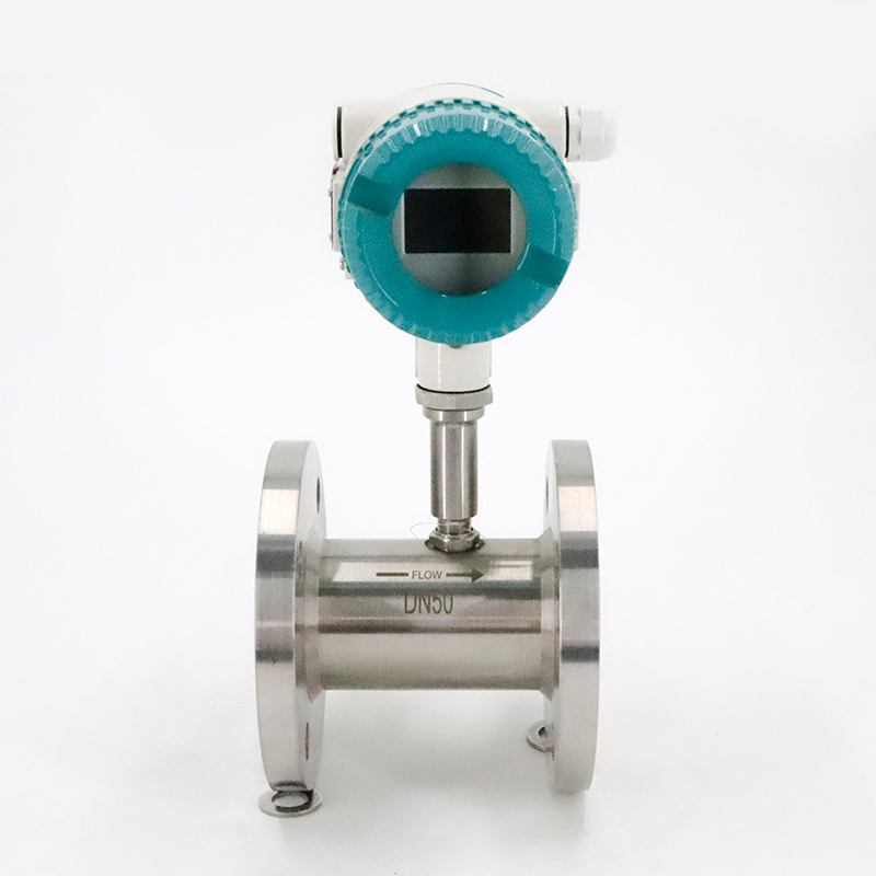

LWLWGY series liquid turbine flowmeter is the main type of velocity flowmeter. When the measured fluid flows through the turbine flowmeter sensor, the impeller is forced to rotate under the action of the fluid, and its speed is proportional to the average flow velocity of the pipeline. At the same time, the blades periodically cut the magnetic lines of force generated by the electromagnet, changing the magnetic flux of the coil. According to the principle of electromagnetic induction, a pulsating potential signal, that is, an electric pulse signal, will be induced in the coil. The frequency of this electric pulse signal is proportional to the flow rate of the measured fluid.
1. Product Features
(1) High accuracy, generally up to ±1%R, ±0.5%R, high-precision type up to ±0.2%R;
(2) Good repeatability. Frequent calibration or online calibration can achieve extremely high accuracy. It is the preferred flow meter in trade settlement.
(3) It has three-point correction of instrument coefficient, intelligent compensation of instrument coefficient nonlinearity, and can be corrected on site;
(4) All valid data will be retained for 10 years after power failure;
(5) Wide range, medium and large diameter can reach 1:20, small diameter is 1:10;
(6) Compact and lightweight structure, easy installation and maintenance, and large flow capacity;
2. Industry Application
In factories, oil fields, chemical industry, metallurgy, food, pharmaceutical industry, loading and other occasions, if used with display instruments with special functions, quantitative control and over-quantity alarm can also be achieved.
3. Technical parameters
Implementation Standards | Turbine flow sensor (JB/T9246-1999) |
Connection | Flange, thread |
Accuracy level | ±1%R; ±0.5%R; ±0.2%R (customizable) |
Sensor Material | 304, 316 stainless steel, etc. |
Conditions of Use | Medium temperature: -20℃~+120℃; Ambient temperature: -20℃~+60℃ |
Relative humidity: 5%-90%; atmospheric pressure: 86KPa~106KPa | |
Signal output function | Pulse signal; 4-20mA signal |
Communication output function | RS485 communication; HART protocol, etc. |
Working power supply | External power supply: 24VDC±15%, ripple ≤±5%, suitable for 4-20mA output, pulse output, RS485, etc. |
Internal power supply: 1 set of 3.6V10AH lithium battery, the battery voltage can work normally when it is 2.0-3.0V | |
Signal line interface | Basic type: Hausmann connector or built-in three-core cable; explosion-proof type, internal thread M20*1.5 |
Explosion-proof grade | EXdbIICT6Gb |
Protection level | IP65 or higher can be customized |
4. Product caliber and flow range comparison table

5. Installation Instructions
The schematic diagram of the installation layout of the turbine flow sensor is shown in the figure.
The turbine flowmeter is packaged separately with the flow sensor, detection components, flow display instrument and other components when it leaves the factory. The steps for on-site installation are as follows:
① Check whether the factory numbers (or instrument coefficients) of sensors, detection components, and flow display instruments are consistent. Do not mix and install components with different factory numbers (or instrument coefficients) to avoid affecting the measurement accuracy.
②Install the sensor assembly on the pipeline according to the installation requirements.
③Fix the detection component to the sensor assembly using threaded connection.
④ Install the flow display instrument assembly on the sensor housing (integral installation), or install the flow display instrument on the pipeline of the sensor accessories.
Installation requirements for pipe sections of liquid turbine flowmeters
Installation of Liquid Turbine Flow Meter
1. When installing the turbine flow sensor, it must be installed in a full pipe, that is, the pipe is full of fluid. Otherwise, the flow measurement will be affected, resulting in measurement errors. When installed horizontally, install as shown in the figure, and when installed vertically, install as shown in the figure.

Liquid turbine flowmeter installation method diagram
2. If the flow sensor is installed at the low point of the pipeline, in order to prevent the precipitation and retention of impurities in the fluid, a discharge valve should be installed in the pipeline behind it to discharge the precipitated impurities regularly.
3. The flow meter is generally installed horizontally. If it needs to be installed vertically, please specify it when ordering.
Liquid turbine flowmeter installation method Figure 2
4. The flow sensor should not be installed at the highest point of the horizontal pipeline, so as to prevent the gas accumulated in the pipeline (such as mixed air when the flow stops) from staying at the flow sensor and being difficult to discharge, thus affecting the measurement. For the correct installation, refer to the figure.
5. The installation method of the sensor is different according to the specifications, and it can be installed by thread or flange. It is strictly forbidden to weld on the flow meter housing. The flow meter must be removed from the pipeline during welding.
6. Before installing the flow meter, clean up the debris, welding slag and dust in the pipeline.
7. In situations where continuous operation is required and flow cannot be stopped, in order to ensure that the normal delivery of the fluid is not affected during maintenance, it is recommended to set up a bypass pipeline and a reliable stop valve at the installation location of the flow sensor according to the diagram. During measurement, ensure that the bypass pipeline is leak-free.
8. When installing the flow meter, the upstream and downstream should be equipped with straight pipe sections of corresponding lengths according to the requirements of the instruction manual. The upstream end of the sensor should have a straight pipe section of at least 20 times the nominal diameter, and the downstream end should have a straight pipe section of at least 5 times the nominal diameter.
9. To ensure the service life of the flow meter, a filter must be installed. For flow that cannot be stopped, two sets of filters should be installed in parallel to remove impurities in turn, or an automatic cleaning filter should be selected.
10. Pay attention to the direction of the fluid during installation and do not install it in reverse.
11. Where a flow control valve is required, the control valve should be installed downstream of the flow meter to reduce flow disturbance from upstream and facilitate stable flow regulation. The upstream stop valve should be fully open during measurement, and these valves should not vibrate or leak outward. The pressure gauge can be installed at the upstream and downstream inlets and outlets, and the thermometer should be installed at 5DN downstream. For pipelines that may produce reverse flow, a check valve should be installed to prevent the fluid from flowing in reverse.
12. When the flow sensor is installed outdoors, please take measures to protect it from the sun and rain.
13. The flow meter casing is equipped with a grounding terminal, which should be reliably grounded, but must not be shared with the ground wire of the high-voltage system.
14. During on-site installation and maintenance, the warning "Do not open the cover when there is explosive gas" must be observed and the external power supply must be turned off before opening the cover.
15. When disassembling or assembling the flowmeter, do not collide with the magnetic induction part.
16. Set the instrument coefficient before putting it into operation. Check carefully to ensure that the instrument wiring is correct and the grounding is good before supplying power.
17. The pipeline where the turbine flowmeter is installed must not impose any stress on it.
18. When conducting a pipeline pressure test, the turbine flowmeter must not be installed on the pipeline.
19. The flow meter display instrument should be able to rotate to a certain angle.