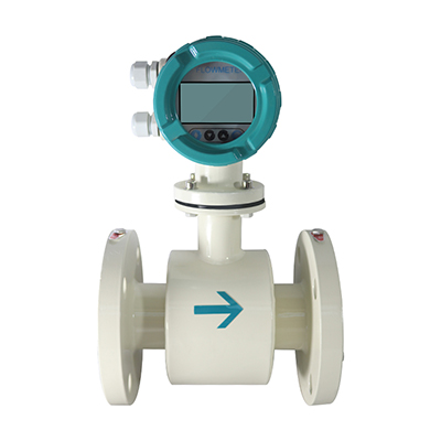

LWLD integrated electromagnetic flowmeter complies with the standard JB/T9248-2015 "Electromagnetic Flowmeter". It is an inductive instrument for measuring the volume flow of conductive media. While performing on-site monitoring and display, it can output standard current signals for recording, adjustment, and control, realize automatic detection control, and can achieve long-distance signal transmission. It can be widely used in the flow measurement of conductive liquids in industries such as tap water, chemical industry, coal, environmental protection, textile, metallurgy, and papermaking.
1. Product Features
(1) Strong independence: the measurement is not affected by changes in physical quantities such as liquid density, viscosity, temperature, pressure and conductivity.
(2) Simple structure, low failure rate, no moving or obstructive parts in the measuring tube, no blockage, and no pressure loss.
(3) It has a wide range of applications and a wide measurement range, and is suitable for conductive liquids and liquids containing fibers, solid particles and suspended matter.
(4) Low installation requirements and straight pipe section requirements (conventionally 10D in front and 5D in the back, 5D in front and 3D in the back for special occasions).
(5) Stable and reliable operation, using low-frequency square wave excitation, low power consumption and stable zero point.
(6) The output signal is diverse and can output linear analog signals, digital signals and alarm signals that are proportional to the flow rate.
2. Industry Application
Flow measurement and control in industrial and agricultural production processes such as petroleum, chemical industry, steel, metallurgy, textile, papermaking, water treatment, environmental sewage monitoring, food and municipal management, water conservancy irrigation, river dredging, etc.
3. Technical parameters
Nominal diameter (mm) (Special specifications can be customized) | Pipeline PTFE lining: DN15~DN600; DN4/DN6/DN10 small diameter needs to be customized |
Pipeline rubber lining: DN50~DN3000 | |
Accuracy level | ±0.5% of the indicated value, optional ±0.3% or ±0.2% of the indicated value |
Repeatability error | ±0.1% of measured value |
Lining material | PTFE, PFA, F46, Neoprene, Polyurethane Rubber, High Temperature Rubber |
Electrode Materials | 316L; Hastelloy B; Hastelloy C; Titanium; Tantalum; Stainless steel coated with tungsten carbide |
Electrode form | Standard |
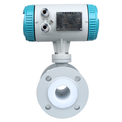
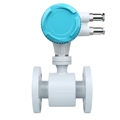
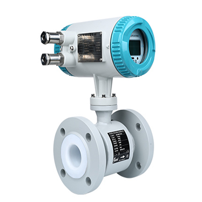
Connection | Flange connection, clamp connection, clamp connection |
Temperature of the medium being measured | Ordinary rubber lining: -20~+60℃ |
High temperature rubber lining: -20~+90℃ | |
PTFE lining: -30~+120℃ | |
High temperature PTFE lining: -20~+180℃ | |
Working conditions | Ambient temperature: -25~+60℃ (liquid in the pipe will not freeze) |
Relative humidity: 5%~90% | |
Nominal pressure | 0.6MPa; 1.0MPa; 1.6MPa; 4.0Mpa (special pressure can be customized) |
Power supply | AC220V or DC24V |
Signal output | Current output 4~20mA (0~750 kΩ), voltage output, |
Pulse output | |
Communication output | RS485, MODBUS protocol, HART protocol |
Total power consumption | Less than 20W |
Dielectric conductivity | ≥20μs/cm |
Ambient humidity | 5~100%RH (Relative humidity) |
Measuring range | 1500:1 Flow rate setting <15m/s |
Protection level | IP65, IP68 optional |
Explosion proof sign | Ex db mbⅡCT6Gb |
Product Standards | JB/T9248-2015 Electromagnetic Flowmeter |
4. Product caliber and flow range comparison table

5. Selection of electrodes and linings
(1) Selection of electrodes

(2) Lining selection

6. Installation Instructions
(1) Places without vibration and strong electromagnetic fields (such as near large motors and inverters);
(2) Install vertically as much as possible. Horizontal installation needs to be installed at a low place and not at the top of the pipe to ensure that the pipe is full and prevent bubbles;
(3) The straight pipe section requirement is to ensure that the front section is 10 times the pipe diameter and the rear section is 5 times the pipe diameter;
(4) When installing by welding, be careful not to connect the instrument by welding to avoid damaging the flow meter;
(5) The outer shell should be grounded as much as possible, the shielded wire should be grounded at one end, and the connection point should not be grounded with strong electricity;
(6) For easy maintenance, the installation location needs to be selected to meet maintenance requirements. At the same time, a bypass pipe can be installed so that the fluid can flow through the bypass pipe in case of failure;
(7) Avoid direct sunlight and high temperature, and make sure to install it in a waterproof and moisture-proof manner;
(8) Other requirements that should be considered: signal lines should not be routed together with high-voltage lines.