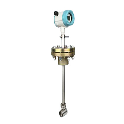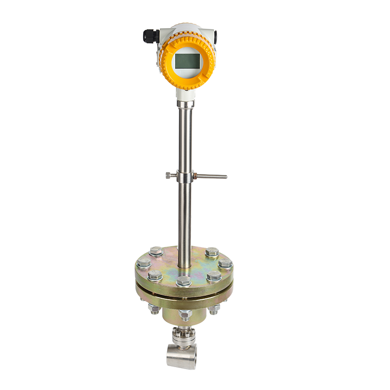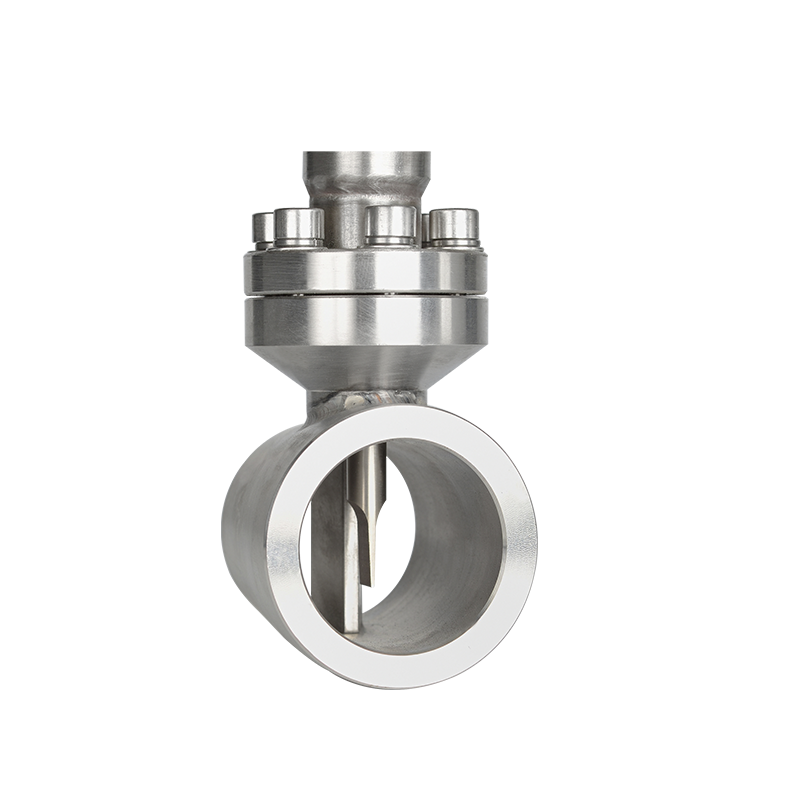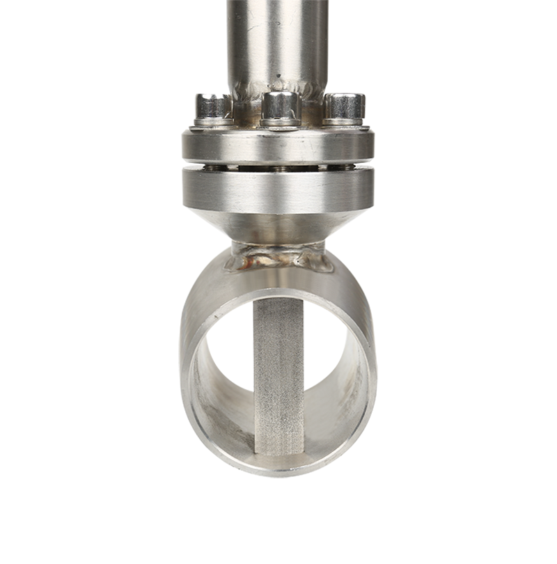

The advantages of LWLUGB series insertion vortex flowmeters are excellent vibration resistance, no zero drift, and high reliability. Through a long period of large-scale waveform analysis and spectrum analysis of vortex flowmeters, better probe shape, wall thickness, height, probe rod diameter and matching piezoelectric crystals are designed, and advanced CNC lathes are used for processing to ensure the coaxiality and finish and other technical parameters of the processing, combined with special process treatment, so as to overcome the common problem of the inherent self-oscillation frequency of vortex flowmeters affecting the signal.
1. Product Features
(1) The structure is simple and strong, with no moving parts, high reliability, and very reliable long-term operation;
(2) Simple installation and convenient maintenance;
(3) The detection sensor does not directly contact the measured medium, with stable performance and long service life;
(4) The output is a pulse signal proportional to the flow rate, with no zero drift and high accuracy;
(5) Wide measuring range, with a range ratio of up to 1:10;
(6) Small pressure loss, low operating cost, and more energy-saving significance;
(7) Within a certain Reynolds number range, the output signal frequency is not affected by changes in the physical properties and components of the fluid. The instrument factor is only related to the shape and size of the vortex generator. No compensation is required when measuring the fluid volume flow rate. Generally, there is no need to recalibrate the instrument factor after replacing accessories.
2. Industry Application
It has a wide range of applications, including steam (saturated steam), gas (air, oxygen, nitrogen, coal gas, natural gas, gas, hydrogen, liquefied petroleum gas, hydrogen peroxide, flue gas, methane, butane, chlorine, fuel gas, biogas, carbon dioxide, nitrogen, acetylene, phosgene, oxygen, compressed air, argon, toluene, benzene, xylene, hydrogen sulfide, sulfur dioxide, ammonia, steam, liquid and water, etc.), liquid (water, high temperature water, oil, food liquid, chemical liquid, etc.), liquid and gas flow.
3. Technical parameters
Measuring medium | Liquid, gas, steam (single-phase medium or can be considered as single-phase medium) | |
When the dryness of saturated steam is ≥85%, it can be considered as a single-phase medium. | ||
Medium temperature | -40℃~+250℃ (350℃ optional) | |
Medium pressure | 1.6MPa 2.5MPa 4.0MPa (pressure above 4.0MPa, special order is required) | |
Accuracy | Level 1.0 Level 1.5 | |
Range Ratio | 1:10 | |
Flow range | Liquid (0.4~7.0) m/s Gas (4.0~60.0) m/s Steam (5.0~70.0) m/s | |
Specification | DN100-DN3000 | |
Material | 1Crl8Ni9Ti | |
Reynolds number | Normal 2x10⁴~7x10⁶ | |
Drag coefficient | Cd≤2.6 | |
Allowable vibration acceleration | LUGB type ≤ 0.2 g | |
Protection level | IP65 | |
Explosion-proof grade | EXdⅡCT6Gb | |
Environmental conditions
| Ambient temperature | (-40~+55)℃ (non-explosion-proof places) (-20~+55)℃ (explosion-proof location) |
Relative humidity | ≤85% | |
Atmospheric pressure | (86~106) kPa | |
Power supply | Non-explosion-proof | (12~32)VDC; 3.6VDC |
4. Product caliber and flow range comparison table
Nominal diameter (mm) | Measuring range (m³/h) | Nominal diameter (mm) | Measuring range (m³/h) | ||
liquid | gas | liquid | gas | ||
100 | 12-200 | 100-1000 | 450 | 350-3500 | 3300-33000 |
125 | 20-300 | 150-1600 | 500 | 450-4500 | 4200-42000 |
150 | 30-400 | 250-2500 | 600 | 600-6000 | 6100-61000 |
200 | 70-700 | 600-6000 | 800 | 800-8000 | 11000-110000 |
250 | 110-1100 | 1060-10600 | 1000 | 1200-12000 | 17000-170000 |
300 | 180-1800 | 1500-15000 | 1200 | 1800-18000 | 24000-240000 |
350 | 210-2100 | 2000-20000 | 1500 | 2600-26000 | 38000-380000 |
400 | 270-2700 | 2700-27000 | >2000 | protocol | protocol |
5. Installation instructions and instructions
① When selecting the installation location of the insertion vortex flowmeter on the pipeline, the length of the upstream straight pipe section should be ≥15D and the downstream straight pipe section should be ≥5D.
② Use gas cutting to open a Φ80mm circular hole in the pipeline. There should be no burrs around the hole to ensure the smooth passage of the probe.
③. Weld the flange short pipe at the circular hole of the pipeline. Pay attention to the vertical direction during welding. After welding, the axis is required to be orthogonal to the axis of the pipeline, and the extension line of the flange short pipe passes through the center of the horizontal surface of the pipeline.
④、The determination of the length Y value of the insertion rod below the lower connecting flange of the vortex flowmeter should be based on the actual factory standard. The user does not need to adjust it. In special cases, when calculating the insertion depth, it should be adjusted appropriately according to the length of the straight pipe section and the working medium. Generally, when the straight section of the measuring pipe is long enough or the diameter of the measuring pipe is above 400mm, the average velocity point measurement method is first used. The measurement accuracy of this method is basically not affected by the change of Reynolds number. The insertion depth of the probe is Y=0.25R-0.25D (R is the radius of the measuring pipe, D is the diameter of the measuring pipe). When the straight section of the measuring pipe is short or the diameter of the measuring pipe is below 400mm (including 400mm), the central velocity point measurement method is used, and the insertion depth is Y=0.5D. After the measurement depth is determined, the length of the insertion rod can be adjusted before installation, and the direction mark of the impact point can be determined to ensure that the direction of the vortex generator is consistent with the flow direction of the measuring pipe according to Figure 3. At this time, the flow meter can be fixed on the flange short pipe with bolts.
⑤. Sealing gaskets should be installed between flanges. Rubber sheets should be used at normal temperature, and asbestos sheets and other heat-resistant materials should be used at high temperature.
⑥. Non-stop flow loading and unloading method (with ball valve): when disassembling, first loosen the set screw, then loosen the locking nut and push the insertion rod upward until the probe is at the upper limit of the ball valve, which just closes the ball valve. Then remove the upper connecting flange, bolts, and nuts, and then remove the flow meter. The order of installing the flow meter is the opposite of that of disassembly.


Figure 1: Schematic diagram of the installation of an insertion vortex flowmeter