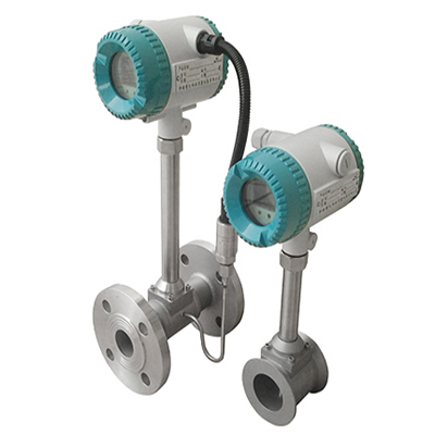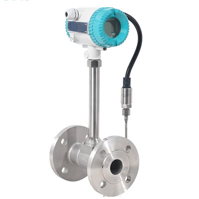

LWLUGB series vortex flowmeter is a volume flowmeter that measures the volume flow rate of gas, steam or liquid, the volume flow rate under standard conditions or the mass flow rate based on the Karman vortex principle. The instrument adopts the differential technology, with isolation, shielding, filtering and other measures, to overcome the problems of poor vibration resistance and small signal data disorder of similar products, and adopts the sensor packaging technology and protection measures to ensure the reliability of the product.
1. Product Features
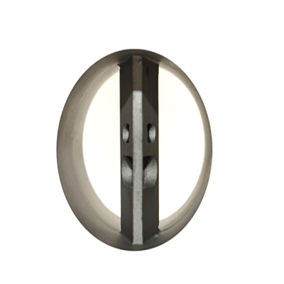
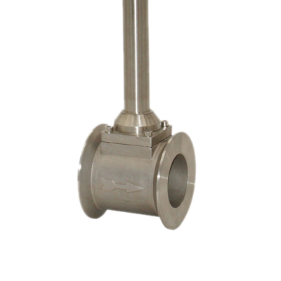
(1) The structure is simple and strong, with no moving parts, high reliability, and very reliable long-term operation;
(2) Simple installation and convenient maintenance;
(3) The detection sensor does not directly contact the measured medium, with stable performance and long service life;
(4) The output is a pulse signal proportional to the flow rate, with no zero drift and high accuracy;
(5) Wide measuring range, with a range ratio of up to 1:10;
(6) Small pressure loss, low operating cost, and more energy-saving significance;
(7) Within a certain Reynolds number range, the output signal frequency is not affected by changes in the physical properties and components of the fluid. The instrument factor is only related to the shape and size of the vortex generator. No compensation is required when measuring the fluid volume flow rate. Generally, there is no need to recalibrate the instrument factor after replacing accessories.
2. Industry Application
It has a wide range of applications, including steam (saturated steam), gas (air, oxygen, nitrogen, coal gas, natural gas, gas, hydrogen, liquefied petroleum gas, hydrogen peroxide, flue gas, methane, butane, chlorine, fuel gas, biogas, carbon dioxide, nitrogen, acetylene, phosgene, oxygen, compressed air, argon, toluene, benzene, xylene, hydrogen sulfide, sulfur dioxide, ammonia, steam, liquid and water, etc.), liquid (water, high temperature water, oil, food liquid, chemical liquid, etc.), liquid and gas flow.
3. Technical parameters
Measuring medium | Liquid, gas, steam (single-phase medium or can be considered as single-phase medium) | |
When the dryness of saturated steam is ≥85%, it can be considered as a single-phase medium. | ||
Medium temperature | -40℃~+250℃ (350℃ optional) | |
Medium pressure | 1.6MPa 2.5MPa 4.0MPa (pressure above 4.0MPa, special order is required) | |
Accuracy | Level 1.0 Level 1.5 | |
Range Ratio | 1:10 | |
Flow range | Liquid (0.4~7.0) m/s Gas (4.0~60.0) m/s Steam (5.0~70.0) m/s | |
Specification | DN15-DN300 | |
Material | 1Crl8Ni9Ti | |
Reynolds number | Normal 2x10⁴~7x10⁶ | |
Drag coefficient | Cd≤2.6 | |
Allowable vibration acceleration | LUGB type ≤ 0.2 g | |
Protection level | IP65 | |
Explosion-proof grade | EXdⅡCT6Gb | |
Environmental conditions
| Ambient temperature | (-40~+55)℃ (non-explosion-proof places) (-20~+55)℃ (explosion-proof location) |
Relative humidity | ≤85% | |
Atmospheric pressure | (86~106)kPa | |
Power supply | Non-explosion-proof | (12~32)VDC;3.6VDC |
4. Product caliber and flow range comparison table
Nominal diameter DN (mm) | Liquid (t=20℃ ρo=1000kg/m3) | Gas (t=20℃ 101325Pa air) | ||
Standard range | Measurable flow range | Standard range | Measurable flow range | |
15 | 0.8-6 | 0.5-8 | 6-40 | 5-50 |
20 | 1-8 | 0.6-12 | 5-50 | 5-60 |
25 | 1.5-12 | 0.8-16 | 8-80 | 8-120 |
32 | 2-20 | 1.5-25 | 15-150 | 10-200 |
40 | 2.5-30 | 1.5-40 | 20-200 | 18-300 |
50 | 3-50 | 2-60 | 30-300 | 30-500 |
65 | 5-80 | 3-90 | 50-500 | 50-900 |
80 | 8-120 | 5-150 | 80-1000 | 60-1200 |
100 | 12-200 | 6-240 | 100-1000 | 100-2000 |
125 | 20-300 | 13-390 | 150-1600 | 150-3000 |
150 | 30-400 | 15-600 | 250-2500 | 200-4000 |
200 | 40-800 | 30-1200 | 400-4000 | 350-8000 |
250 | 80-120 | 40-1600 | 600-6000 | 500-1200 |
300 | 100-1800 | 50-2000 | 1000-10000 | 600-18000 |
5. Installation instructions and instructions
(1) The sensor should be installed horizontally or vertically (liquid flows from bottom to top) on a pipe with a corresponding nominal diameter.
(2) A certain length of straight pipe section should be configured upstream and downstream of the sensor, and its length should meet the requirements shown in the following table.
Straight pipe length configuration
Upstream pipeline type | Upstream straight pipe length | Downstream straight pipe length |
Concentric pipe full open gate valve | ≥12DN |
≥5DN
|
Concentric contraction fully open gate valve | ≥15DN | |
A 900 elbow | ≥20DN | |
Two 900 elbows on the same plane | ≥25DN | |
Two 900 elbows in different planes | ≥40DN | |
Regulating valve, half-open gate valve | ≥50DN |
(3) No flow control valve should be installed on the upstream side of the sensor
(4) If the length of the upstream straight pipe section cannot meet the requirements of the above table, it is recommended that the user install a fluid rectifier in the upstream side pipeline.
(5) The sensor should not be installed on a pipeline with strong vibration to avoid affecting the accuracy. If the sensor is installed and used on a vibrating pipe section, the following measures can be taken to reduce the interference caused by vibration;
a. Install a pipe fixing support point 2D upstream of the sensor
b. Install a hose transition under the premise of meeting the straight pipe section requirements
(6) When the sensor is installed on a high-temperature pipe, if the insulation is not good, the sensor must be installed vertically downward.
(7) The vortex flow sensor is not allowed to be hit by hard objects during installation, otherwise it will affect the measurement accuracy or even damage the instrument.
(8) When the measured medium needs to be corrected for temperature and pressure, a pressure point should be made 3-5DN behind the sensor, and a temperature point should be made 5-8DN behind the sensor, as shown in the flow meter installation diagram below.