


The design, testing and power supply of the flowmeter are subject to safety regulations. Users must strictly abide by the relevant clauses of this manual to ensure the safe operation and operation of the flowmeter. The necessary conditions to ensure the measurement accuracy of the electromagnetic flowmeter are as follows:
The liquid medium to be measured must be conductive.
The measured liquid medium must fill the pipe.
The measured liquid medium must be uniform to avoid conductivity inhomogeneity (which will cause serious interference). If chemical substances need to be added dynamically, they should be injected downstream of the instrument.
The electromagnetic flowmeter system must be well grounded.
The straight pipe section at the inlet of the flowmeter should be at least 5 times DN (inner diameter of the measuring pipe), and the straight pipe section at the outlet should be at least 2 times DN. Avoid strong electromagnetic interference near the flowmeter, and avoid installing it near large motors or transformers.
Safety measures
To ensure personal and equipment safety, the following terms must be observed:
Before selecting a location and installing the flow meter, you must carefully read the relevant parts of this manual and consider the safety requirements of the flow meter, related equipment and the environment.
The installation and maintenance of the instrument should be carried out by personnel with certain instrument knowledge.
Correctly install the flow meter sensor and piping to ensure safe and reliable sealing. The liquid pressure shall not exceed the maximum working pressure specified on the nameplate.
Take certain measures to prevent electric shock accidents.
The lifting equipment of the flow meter should comply with safety regulations.
1. Precautions for installing sewage flow meter:
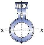
There are no particularly strict requirements for the installation direction of the sewage flow meter. Generally, it can be horizontal, vertical or inclined without restriction. However, it must be reminded that in order to ensure that the pipe is full of the measured medium, that is, the "full pipe" state, it is recommended to install it vertically, with the flow direction from bottom to top, especially for liquid-solid two-phase fluids, which must be installed vertically. If only horizontal installation is allowed on site, it is necessary to ensure that the two electrodes are on the same horizontal plane, and the axis of the electrode must be approximately horizontal, because the electrode at the bottom is easily covered by sediments, and the top electrode is easily rubbed by occasional bubbles in the liquid, covering the electrode surface and causing the output signal to fluctuate. The following are matters that need to be paid attention to in the installation of sewage flow meters:
1. There should be at least a 5DN straight pipe section upstream of the flow meter and at least a 3DN straight pipe section downstream. In order to facilitate installation and disassembly, a pipe expansion joint can be installed when the flow meter leaves the factory;
2. The flow direction of the fluid is consistent with the arrow direction on the flow meter housing;
3. If there is negative pressure in the pipeline, it will damage the internal lining material of the flow meter. Special attention should be paid to prevent negative pressure. For example, if the liquid temperature is higher than the room temperature, after closing the upstream and downstream stop valves of the sensor to stop operation, the fluid will cool and shrink to form negative pressure. A negative pressure prevention valve should be installed near the sensor;
4. The flow meter should be kept as far away from pumps, valves and other equipment as possible to avoid interference with the measurement;
5. The flow meter should be kept as far away from interference sources such as radio frequency, strong magnetic field, strong vibration, etc.
6. If the measuring pipeline vibrates, there should be fixed supports on both sides of the flow meter;
7. When measuring mixed phase fluids, choose a location that will not cause phase separation; when measuring two-component liquids, avoid installing it downstream where the mixture is not yet uniform; when measuring chemical reaction pipelines, install it downstream of the reaction section where the reaction is fully completed; when measuring mixed phase fluids, the distance between the mixing point and the flow meter must be at least 30DN of straight pipe section;
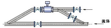
8. To facilitate the cleaning and maintenance of the flow meter in the future, a bypass pipe should be installed, and a straight pipe section of 5DN before the flow meter and 3DN after the flow meter should be ensured;
9. When installing the sewage flow meter, pay attention to tightening the two flanges evenly, otherwise it is easy to crush the lining material. It is best to use a torque wrench;
10. The sensor must be grounded separately. In general, the grounding resistance should be below 100 ohms. For explosion-proof products and lightning protection installations, the grounding resistance should be less than 10 ohms. In principle, the grounding of the split flow meter should be on the sensor side, and the converter grounding should be at the same grounding point;
11. The split-type sewage flow meter converter is generally installed near the sensor or in the distribution room. It should be noted that when the sensor is connected to the converter, in order to avoid signal interference, the signal cable must be separately passed through the grounded protection metal pipe, and the signal and power cables cannot be mixed in the same metal pipe.
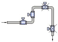
2. Sewage flow meter installation example diagram and requirements:
1. It should be installed at the lower part of the horizontal pipe and vertically upward, and avoid installation at the highest point of the pipe and vertically downward;
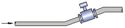
2. It should be installed at the rising part of the pipe;
3. When installed in an open discharge pipe, it should be installed at the lower part of the pipe;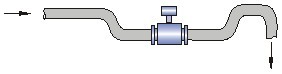
4. If the pipe drop exceeds 5m, install an exhaust valve downstream of the sensor;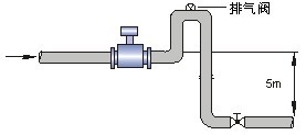
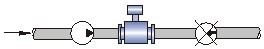
5. The control valve and cut-off valve should be installed downstream of the sensor, not upstream of the sensor;
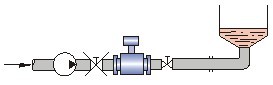
6. The sensor cannot be installed at the inlet and outlet of the pump, but should be installed at the outlet of the pump;
7. How to install a liquid flow meter in a measuring well;
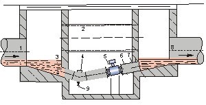
Figure 7 Notes: 1. Inlet 2. Overflow pipe 3. Inlet grid 4. Cleaning hole 5. Flow meter 6. Short pipe 7. Outlet 8. Discharge valve
How to correctly select the installation node:
Correctly selecting the installation point and correctly installing the flow meter are very important links. If there is a mistake in the installation link, the measurement accuracy will be affected at the least, and the service life of the flow meter will be affected at the worst, and the flow meter may even be damaged.
When choosing the installation location, special attention should be paid:
the axis of the non-measuring electrode must be approximately horizontal;
the measuring pipe must be completely filled with liquid;
there must be at least a straight pipe section of 5×D (D is the inner diameter of the flowmeter) in the front and a straight pipe section of 3×D (D is the inner diameter of the flowmeter) in the back;
the flow direction of the fluid is consistent with the arrow direction of the flowmeter;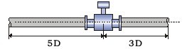
there must be a vacuum in the pipe, which will damage the lining of the flowmeter, so special attention should be paid;
there should be no strong electromagnetic field near the flowmeter;
there should be ample space nearby for installation and maintenance;
if the measuring pipe vibrates, there should be fixed supports on both sides of the flowmeter. When measuring mixed liquids of different media, the distance between the mixing point and the flowmeter must be at least 30×D (D is the inner diameter of the flowmeter). In order to facilitate the cleaning and maintenance of the flowmeter in the future, a bypass pipe should be installed;