

Abstract: Based on the analysis of the influence of excitation signal on metering accuracy, a new excitation signal form is proposed to improve the metering accuracy of mud in view of the characteristics of high-density and large-displacement mud pipe flow field in cementing operations and the interference characteristics of the construction site. The field verification results are given.
The purpose of cementing is to use cement to establish interlayer isolation. First of all, it must be able to effectively remove drilling fluid from the wellbore. Under the premise of ensuring underground safety, the mud is injected at high pressure and the construction flow is controlled to achieve effective displacement. Improving the displacement efficiency of the injected cement is the basic premise for avoiding drilling fluid channeling and ensuring the cement bonding quality and ring sealing effect. The flow rate of mud is an important parameter in the cementing construction process. Continuous, real-time and accurate measurement of it is a necessary means to ensure cementing quality, improve construction technology level and efficiency, and achieve scientific management.
Due to the wide range of physical properties and composition of cementing mud, several detection instruments and methods currently used have many problems. For example, although the Coriolis mass flowmeter has high measurement accuracy, it is very sensitive to external vibration, needs to be fixedly installed, and has poor pressure resistance, so it cannot be used for real-time measurement of high-pressure operations; ultrasonic flowmeters are most closely related to physical properties and composition, and are difficult to promote and use at cementing sites; there are also reports of using electromagnetic flowmeters to measure cementing mud, but the pressure resistance (≤5MPa) and mud density (≤1.8g/cm³) have certain limitations, and cannot be used to accurately measure the mud flow of different physical properties and components on site. At present, most oil fields use turbine flowmeters to measure the flow of cementing mud on site. Although its flow accuracy (3%) can meet the requirements, the turbine is often blocked by debris in the mud (especially for high-density mud), affecting construction, and the flushing and bearing maintenance requirements are high, and the life is not long. With the increasing number of deep drilling operations in my country, high-density and large-displacement muds are used more and more frequently in cementing construction, and a new type of mud flowmeter is needed for real-time and accurate measurement on site.
Starting from the principle of conventional electromagnetic flowmeter, on the basis of analyzing the influence of excitation signal on metering accuracy, this paper proposes a new excitation signal form according to the characteristics of high-density and large-flow mud pipe flow field at cementing construction site to improve the metering accuracy of cementing mud. Finally, the field verification results are given.
1. Measurement principle
According to Faraday's law of electromagnetic induction, when a conductor moves in a magnetic field and cuts the magnetic lines of force, an induced electromotive force will be generated at both ends of the conductor. In a uniform magnetic field, assume that there is a non-magnetic pipe with a diameter of D perpendicular to the direction of the magnetic field, with an insulating lining cast on the inner surface and a coil wound on the outer surface. A pair of detection electrodes are installed on the pipe wall perpendicular to the axis of the metering pipe and the magnetic lines of force of the magnetic field. The mud used for cementing is a conductive medium. When the mud flows in the measuring pipe, the magnetic field generated by the excitation current in the coil will be cut by the mud, which will generate an induced electromotive force E proportional to the average flow velocity v of the mud.
E=BDv (1)
Where B is the magnetic induction intensity.
The volume flow rate of the pipeline can be obtained as follows:
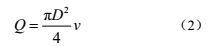
From formula (1) and formula (2), we can get:
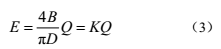
Where: K is the instrument constant. When the magnetic induction intensity B is kept constant, the volume flow rate Q of the pipeline can be obtained by measuring the induced electromotive force E, and there is a linear relationship.
2. Excitation method
From the measurement principle, we know that only when the measuring pipeline maintains a uniform and constant magnetic field, that is, B is a constant, the linear relationship between the volume flow rate Q and the induced electromotive force E holds true, so it is necessary to choose a suitable excitation method.
Excitation technology is a critical technology in electromagnetic flowmeters. Currently, three methods are generally used: DC excitation, industrial frequency sinusoidal excitation, and low-frequency square wave excitation. DC excitation uses direct current or permanent magnets to generate a magnetic field. Although the structure is simple, the electrode is prone to polarization, and it is difficult to ensure that B is a constant, which limits its application range. Industrial frequency sinusoidal excitation generates an alternating magnetic field through the excitation coil, but it is easy to produce orthogonal interference and in-phase interference, etc., causing zero drift. Low-frequency square wave excitation uses a low-frequency square wave to excite the coil after power amplification to generate a magnetic field. Within half a cycle, the magnetic field is a constant DC magnetic field, which is little affected by electromagnetic interference, and eliminates the industrial frequency interference caused by distributed capacitance; at the same time, from the entire time process, the square wave signal is an alternating signal, which overcomes the * phenomenon that is easy to produce by DC excitation. At present, this excitation method is widely used in electromagnetic flowmeters.
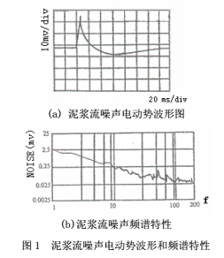
The excitation current frequency of the low-frequency square wave excitation method used in conventional electromagnetic flowmeters is usually 1/4 to 1/10 of the power frequency. At present, the density of the mud used in cementing construction of deep wells (above 6000m) is mostly above 1.8g/cm³, and the flow rate is as high as 25m/s. The mud used is a solid-liquid two-phase low-conductivity fluid. Although the measurement error caused by non-Newtonian fluid can be eliminated under high pressure, random interference noise with increasing frequency as the flow rate increases will be generated in the measuring tube. It has been determined that in the DN50 measuring tube, the mud density used is 2.0g/cm³, the flow rate is in the range of 10 to 15m/s, and the flow noise in the measuring tube is mainly peak-shaped mud flow noise, with an order of magnitude of mv and a frequency concentration below 25Hz, as shown in Figure 1. When the excitation frequency is low, the order of magnitude of mud interference is large, and the order of magnitude of interference is small at high frequencies, with a 1/f spectrum characteristic. In addition, the low-frequency noise caused by knocking and vibration at the construction site will also affect the measurement accuracy of the electromagnetic flowmeter. Increasing the excitation current frequency can circumvent and suppress these interferences to improve the signal-to-noise ratio of the electromagnetic flow sensor output, but it will sacrifice the zero point stability of the electromagnetic flowmeter. This paper proposes a new excitation method, using a dual-frequency rectangular wave as the excitation signal. The excitation current waveform is a high-frequency rectangular wave superimposed on a low-frequency rectangular wave, and two sampling frequencies are used to obtain high-frequency and low-frequency flow signals respectively. As shown in Figure 2, the high-frequency part is an 80Hz rectangular wave, and the outer envelope is a 10Hz low-frequency rectangular wave. In this way, the mud flow noise existing in the single low-frequency rectangular wave excitation can be overcome, while ensuring the stability of the zero point, and improving the metering stability and response speed of the flowmeter.
3. Hardware system
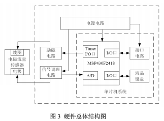
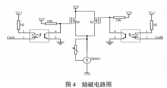
The hardware part of the electromagnetic flowmeter used for cementing mud is mainly composed of modules such as sensor, power supply circuit, excitation circuit, signal conditioning circuit, signal acquisition and processing circuit and interface circuit, as shown in Figure 3. This article focuses on the key modules of excitation circuit and signal conditioning circuit.
3.1 Excitation circuit
The excitation circuit determines the working magnetic field of the instrument and is an extremely critical part of the instrument. The excitation circuit in this article consists of two parts, as shown in Figure 4. The timer of the single-chip microcomputer MSP430F2418 generates a dual-frequency rectangular wave, which is isolated by an optocoupler and then connected to the on-off function by a switch circuit composed of two field effect transistors. The DH902 is a constant current tube that provides a constant excitation current. The pulse width modulation (PWM) output of the MCU timer is filtered to control the amplitude of the excitation current, thereby generating a dual-frequency rectangular wave.
3.2 Signal Conditioning Circuit
The induced electromotive force signal output by the electrode is an alternating signal of microvolt to millivolt level. After filtering, some high-frequency signals are removed, and then sent to a high-impedance amplifier for amplification. The high-frequency and low-frequency signals are respectively taken out through a two-stage bandpass filter. After DC isolation, the AC component is retained and sent to the ADC pin of the MCU.
4. Software system
The system software adopts a modular design method and consists of a control module, a measurement module, an empty pipe detection module and an analysis software. The control module is the main program of this instrument, which is used to generate dual-frequency rectangular excitation waves, control the collection and processing of flow signals, and use the keyboard operation and LCD display in menu mode to make the instrument enter the parameter setting state or the working condition display state. The measurement module collects the flow signal from the signal conditioning module, calculates the instantaneous flow, cumulative flow and flow velocity, and performs the corresponding instrument coefficient compensation, which is displayed on the LCD screen and output by the interface. The empty pipe detection module is used to set the geomagnetic amplitude of the actual environment and detect whether the measuring pipe is in an empty pipe state. The analysis software is used to automatically generate various reports and icons required for cementing construction from the metering data.
5. Test results and analysis
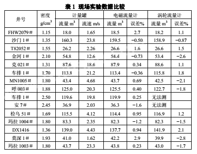
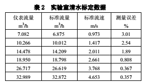
The inner diameter of the measuring tube used in the field test is DN50. It is connected to the mud pipeline through a high-pressure union and connected in series with a turbine flowmeter for comparison. The standard metering tank test is used. The metering drilling mud density range is 1.15g/cm³~2.50g/cm³, the one-time slurry replacement volume at the cementing design construction site is 18m³~160m³, and the instantaneous slurry replacement flow rate is 0.2m³/min~2.8m³/min (flow rate: 1.6~23.8m/s); through the construction application of nearly 15 wells, the results are shown in Table 1. The test shows that the metering error of the instrument is less than 1%; below the flow rate of 2.0m/s, the test error gradually increases with the decrease of the flow rate, and the metering accuracy drops to about 3% at a flow rate of about 1.0m/s. After analysis, it is mainly caused by zero drift, which is basically consistent with the laboratory calibration results with clean water. Using a DN50 measuring tube, the laboratory calibration results are shown in Table 2. Experiments have shown that the use of dual-frequency rectangular waves as excitation signals can effectively avoid and suppress low-frequency noise caused by flow noise and field vibration of cementing mud, thereby significantly improving the accuracy of instrument measurement of mud.
6. Conclusion
This paper uses a dual-frequency rectangular wave as the excitation signal. According to the characteristics of cementing construction and the analysis of on-site interference, the appropriate excitation current frequency is selected to improve the anti-interference ability of the instrument during the working process, which significantly improves the metering accuracy of cementing mud. Since the measuring tube is a smooth pipe without flow-blocking detection parts, it is impossible to be blocked by debris in the mud (especially for high-density mud) and affect the construction, and the flushing and maintenance requirements are very low, which has a good promotion and application value. In the future, the form of the excitation signal and the selection of the excitation current frequency will be further studied to improve the measurement accuracy of the instrument in the low flow rate stage.