

Determination of instrument caliber and installation design
Instrument selection is a very important task in instrument application. The correctness of instrument selection will directly affect whether the instrument can operate normally. Therefore, when users and design units select our company's products, please read this section carefully, check the process parameters of the fluid carefully and contact our sales or technical support department to ensure the correct selection.

1. Determination of applicable flow range and instrument caliber
The selection of the instrument caliber is determined by the flow range. The measurement range of vortex flow meters of different calibers is different. Even if the same caliber flow meter is used for different media, its measurement range is different. The actual measurable flow range needs to be determined by calculation.
(I) The flow range of air and water under reference conditions is shown in Table (II). The reference conditions are as follows:
1. Gas: air at normal temperature and pressure, t=20℃, P=0.1MPa (absolute pressure), ρ=1.205 kg/m3, υ=15×10-6 m2/s
2. Liquid: water at room temperature, t = 20 ° C, ρ = 998.2 kg/m3, υ = 1.006 × 10⁻⁶ m2/s.
(II) Basic steps to determine flow range and instrument caliber:
1. Define the following working parameters.
(1) Name and composition of the medium being measured
(2) Minimum, normal and maximum flow rates in working state
(3) Minimum, common, and maximum pressures and temperatures of the medium
(4) Viscosity of the medium under working conditions
2. The vortex flowmeter measures the working volume flow of the medium, so the working volume flow of the medium should be calculated based on the process parameters. The relevant formula is as follows:
(1) If the standard gas volume flow rate is known, the following formula can be used to calculate the standard gas volume flow rate:
The working volume flow rate is calculated by
Formula (3)
(2) Given the standard state density ρ of a gas, it can be obtained by the following formula:
The working condition density is calculated by
Formula (4)
(3) Convert the known mass flow rate Qm to the volume flow rate Qv
Formula (5)
Where:
Qv: Volume flow rate of medium under working conditions (m3/h)
(Qv=3600f/K K: instrument factor)
Qo: Volume flow rate of medium under standard conditions (Nm3/h)
Qm: mass flow rate (t/h)
ρ: Density of the medium under working conditions (kg/m3)
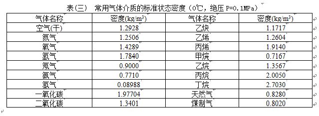
ρo: Density of the medium under standard conditions (kg/m3). For the density of commonly used gaseous media under standard conditions, see Table (III)
P: operating state gauge pressure (MPa)
t: operating temperature (℃)
3. Determination of the lower limit flow rate of the instrument. The upper limit applicable flow rate of the vortex flowmeter is generally not calculated. The selection of the caliber of the vortex flowmeter is mainly based on the calculation of the lower limit flow rate. The calculation of the lower limit flow rate should meet two conditions: the minimum Reynolds number should not be lower than the limit Reynolds number (Re=2×10⁴); for the stress-type vortex flowmeter, the vortex intensity generated at the lower limit flow rate should be greater than the allowable value of the sensor vortex intensity (the vortex intensity is proportional to the lift ρv2). These conditions can be expressed as follows:
The measurable lower limit flow rate under working conditions determined by density is:
Linear lower limit flow rate determined by kinematic viscosity:
Formula (7)
Where:
Qρ: Minimum volume flow rate to meet vortex intensity requirements (m3/h)
ρ0: Density of the medium under reference conditions
Qυ: Minimum linear volume flow rate that meets the minimum Reynolds number requirement (m3/h)
ρ: Working density of the measured medium (kg/m3)
Q0: Minimum volume flow rate of the instrument under reference conditions
(m3/h)
υ: Kinematic viscosity of the medium under working conditions (m2/s)
υo: Kinematic viscosity of the medium under reference conditions (m2/s)
Qρ and Qν are calculated by formula (6) and (7). Compare Qρ and Qν to determine the measurable lower limit flow rate and linear lower limit flow rate of the flow meter:
Qυ≥Qρ: The measurable flow range is Qρ~Qmax, and the linear flow range is Qυ~Qmax
Qυ<qρ: The measurable flow range and linear flow range are <div="">
Qρ~Qmax
Qmax: The upper limit volume flow rate of the vortex flow meter (m3/h)
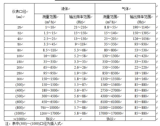
4. The upper limit flow rate of the instrument shall be based on the upper limit flow rate in Table (II). The upper limit flow rate of gas should be less than 70m/s, and the upper limit flow rate of liquid should be less than 7m/s
5. When the medium measured by the user is steam, the commonly used measurement unit is mass flow, that is, t/h or Kg/h. Since the density of steam (superheated steam and saturated steam) is different at different temperatures and pressures, the steam flow range can be determined by formula (8)
Formula (8)
Where:
ρ: density of steam (kg/m3)
ρ0: 1.205kg/m3
Q steam: steam mass flow rate (t/h)
6. Calculate the pressure loss and check whether the pressure loss has any effect on the process pipeline. The formula (unit: Pa) is:
Δp = CdρV2/2 Formula (9)
Where:
Δp: pressure loss (Pa) Cd: pressure loss coefficient
ρ: working medium density (kg/m3) V: average flow velocity (m/s)
7. When the measured medium is liquid, in order to prevent gasification and cavitation, the pipeline pressure should meet the following requirements:
p≥2.7Δp+1.3p0 formula (10)
Where:
Δp: Pressure loss (Pa)
p0: saturated vapor pressure of liquid at working temperature (Pa absolute pressure)
Po: Vapor pressure of fluid (Pa absolute pressure)
8. Vortex flowmeter is not suitable for measuring high viscosity liquids. When the calculated measurable flow rate lower limit does not meet the design process requirements, other types of flowmeters should be considered.
9. If two calibers can meet the requirements through calculation, in order to improve the measurement effect and reduce the cost, the smaller caliber meter should be selected. It should be noted that the commonly used volume should be within 1/2 to 2/3 of the upper limit of the flow range as much as possible.
Table (II) Flow range of vortex flow sensor under reference conditions
(III) Selection examples:
Example 1: When the gas pressure, temperature and flow rate under standard conditions are known
For a certain compressed air, the standard flow range is QN=1200-12000Nm3/h, the pressure P=0.7Mpa (gauge pressure), and the temperature t=30℃. Try to determine the flow meter diameter.
Step 1: Calculate the operating volume flow rate of compressed air
According to formula (3):
The lower limit volume flow rate for working conditions is:
Qvmin=QN×0.101325×(273.15+t)/293.15/(P +0.1)
=1200×0.101325×(273.15+30)/293.15/(0.7 +0.1)
=157(m3/h)
The upper limit of the working flow rate is: Qvmax=1570(m3/h)
Step 2: According to the flow range of 157-1570m3/h, check Table (II). The flow meters that meet the lower limit flow condition are DN80, DN100 and DN125. Considering the upper limit flow of 1270m3/h and the use effect and economic cost, DN100 is initially selected. The working flow range of DN100 flowmeter is 100-1700m3/h, which is close to the working flow range. DN100 flowmeter is initially selected, but the measurable lower limit flow of DN100 flowmeter under this working condition should be specifically calculated. Calculate the measurable lower limit flow of DN100 flowmeter under this working condition:
From formula (4) and formula (6):
37.46(m3/h)
That is, the measurable lower limit flow rate of the flowmeter under this working condition is
37.46m3/h, which is far less than the required lower limit flow rate of 157m3/h under the working condition, so it is decided to use a DN100 flow meter.
Example 2: When the steam pressure, temperature and operating flow are known
The measuring medium is superheated steam, the steam temperature is 320℃, the pressure is 1.5MPa (absolute pressure), the flow range is 3t/h~25t/h, try to determine the flowmeter caliber.
Step 1: Calculate the volume flow range of steam under equivalent air reference conditions. According to Appendix (II), the density of steam under this condition is 5.665Kg/m3. According to formula (8):
765(m3/h)
6379(m3/h)
Step 2: According to the equivalent reference flow range of 765-6379m3/h, check Table (2) and the most suitable flow range is DN200.
The correct installation of the instrument is an important part of ensuring its normal operation. Improper installation may affect the accuracy of the instrument at best, or even affect its service life or damage it at worst.
1. Installation environment requirements:
1. Avoid strong electric equipment, high frequency equipment, and strong switching power supply equipment as much as possible. The power supply of the instrument should be separated from these equipment as much as possible.
2. Avoid direct influence of high temperature heat source and radiation source. If installation is necessary, heat insulation and ventilation measures must be taken.
3. Avoid high humidity environment and strong corrosive gas environment. If installation is necessary, ventilation measures must be taken.
4. The vortex flowmeter should be installed as far as possible on pipelines with strong vibration. If it must be installed, a pipeline fastening device must be added 2D upstream and downstream, and anti-vibration pads must be added to enhance the anti-vibration effect.
5. The instrument is best installed indoors. If installed outdoors, attention should be paid to waterproofing. In particular, the cable should be bent into a U shape at the electrical interface to prevent water from entering the amplifier housing along the cable.
6. Sufficient space should be left around the instrument installation point to facilitate installation, wiring and regular maintenance.
(II) Instrument pipeline installation requirements:
1. The vortex flow meter has certain requirements for the upstream and downstream straight pipe sections of the installation point, otherwise it will affect the flow field of the medium in the pipeline and affect the measurement accuracy of the meter. The requirements for the upstream and downstream straight pipe section lengths of the meter are shown in Figure (III).
DN is the instrument diameter
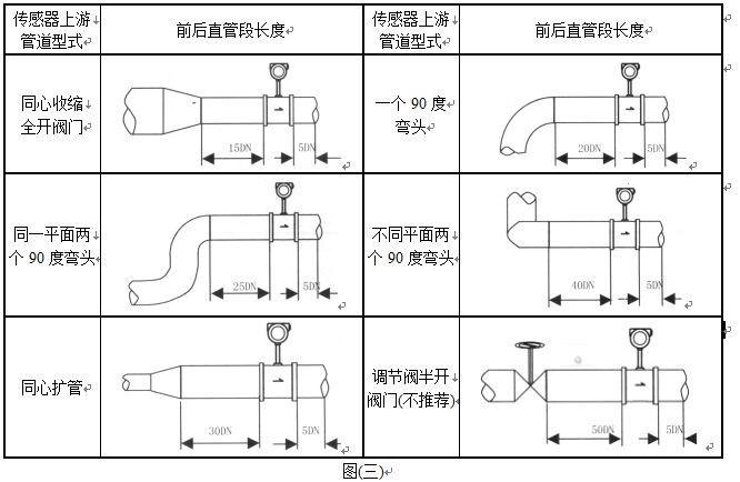
Note: The regulating valve should not be installed upstream of the vortex flowmeter as much as possible, but should be installed 10D downstream of the vortex flowmeter.
2. The inner diameters of the upstream and downstream piping should be the same. If there is a difference, the inner diameter of the piping Dp and the inner diameter of the vortex meter body Db should satisfy the following relationship:
0.98Db≤Dp≤1.05Db
The upstream and downstream piping should be concentric with the inner diameter of the flow meter body, and the misalignment between them should be less than 0.05Db
3. The sealing gasket between the meter and the flange should not protrude into the pipe during installation, and its inner diameter should be 1-2mm larger than the inner diameter of the meter body.
4. Installation design of pressure measuring holes and temperature measuring holes. When the measured pipeline needs to install temperature and pressure transmitters, the pressure measuring hole should be set at 3-5D downstream, and the temperature measuring hole should be set at 6-8D downstream, as shown in Figure (VII). D is the instrument diameter, unit: mm
5. The instrument can be installed horizontally, vertically or inclined on the pipeline.
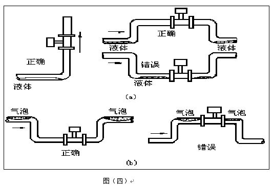
6. When measuring gas, install the instrument in a vertical pipeline, and the gas flow direction is not limited. However, if the pipeline contains a small amount of liquid, in order to prevent the liquid from entering the instrument measuring tube, the gas flow should flow from bottom to top, as shown in Figure (IV) a
7. When measuring liquid, in order to ensure that the pipe is full of liquid, when installing the meter on a vertical or inclined pipeline, the liquid flow direction should be from bottom to top. If there is a small amount of gas in the pipeline, in order to prevent the gas from entering the meter measuring tube, the meter should be installed at the lower part of the pipeline.
As shown in Figure (IV) b
8. When measuring high-temperature and low-temperature media, attention should be paid to heat preservation measures. The high temperature inside the converter (inside the meter housing) should generally not exceed 70°C; low temperature is prone to condensation inside the converter, reducing the insulation resistance of the printed circuit board and affecting the normal operation of the instrument.