

Liquid flow meter installation

1. Installation Instructions
The design, testing and power supply of the flowmeter are subject to safety regulations. Users must strictly abide by the relevant clauses of this manual to ensure the safe operation and operation of the flowmeter. The necessary conditions to ensure the measurement accuracy of the electromagnetic flowmeter are as follows:
The liquid medium to be measured must be conductive.
The liquid medium to be measured must fill the pipe.
The measured liquid medium must be uniform to avoid conductivity inhomogeneity (which will cause serious interference). If chemical substances need to be added dynamically, they should be injected downstream of the instrument.
The electromagnetic flowmeter system must be well grounded.
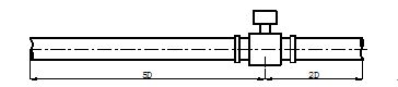
The straight pipe section at the flow meter inlet should be at least 5 times DN (inner diameter of the measuring pipe), and the straight pipe section at the outlet should be at least 2 times DN.
Avoid strong electromagnetic field interference near the flow meter and avoid installing it near large motors, transformers and other equipment.
2. Safety measures
To ensure personal and equipment safety, the following terms must be observed:
Before selecting a location and installing the flow meter, you must carefully read the relevant parts of this manual and consider the safety requirements of the flow meter, related equipment and the environment.
The installation and maintenance of the instrument should be carried out by personnel with certain instrument knowledge.
Correctly install the flow meter sensor and piping to ensure safe and reliable sealing. The liquid pressure shall not exceed the maximum working pressure specified on the nameplate.
Take certain measures to prevent electric shock accidents.
The lifting equipment of the flow meter should comply with safety regulations.
3. Inspection before installation
Check flange, lining, housing and lead sleeve for damage.
Open the box cover and check whether the wiring printed circuit board is loose or damaged.
Check whether the model code in the inscription* matches the order code.
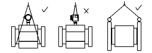
4. Hoisting
The flowmeter should be hoisted using the correct hoisting method, and the safe load and protective measures of the hoisting equipment should comply with relevant regulations. It is prohibited to use ropes to tie the instrument to the converter box (integrated flowmeter) or the junction box (separate flowmeter).
5. Choose the correct installation location
Correctly selecting the installation location and correctly installing the flow meter are both very important links. If errors are made during the installation process, the measurement accuracy may be affected at best, and the service life of the flow meter may be affected at worst, or even the flow meter may be damaged. When selecting the installation location, the following issues should be noted:
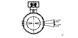
The axis of the measuring electrode must be approximately horizontal (the angle with the horizontal line is generally within 10°).
The measuring tube must be completely filled with liquid.
There should be at least 5×D (D is the inner diameter of the flow meter) straight pipe section in front of the flow meter and at least 2×D (D is the inner diameter of the flow meter) straight pipe section in the back.
The length of the straight pipe section is (the inner diameter of the flow meter).
The flow direction of the fluid is consistent with the arrow direction of the flow meter.
Vacuum in the pipeline will damage the lining of the flow meter, so special attention should be paid.
There should be no strong electromagnetic field near the flow meter, and the magnetic field strength at the installation site should be less than 400A/m (avoid installing it in a large
near equipment such as motors or transformers).
If the measuring pipeline vibrates, there should be fixed supports on both sides of the flow meter.
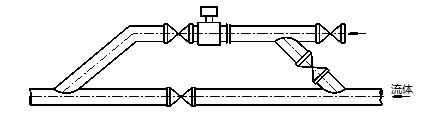
When measuring a mixture of different media, the distance between the mixing point and the flow meter must be at least 30×D (D is the inner diameter of the flow meter).
In order to facilitate the cleaning and maintenance of the flow meter in the future, a bypass pipe should be installed.
When installing a flowmeter with a PTFE liner, the bolts connecting the two flanges should be tightened evenly, otherwise the PTFE liner will be easily crushed. It is best to use a torque wrench.
The instrument should be protected from strong vibration and excessive temperature changes, and should also be protected from dripping corrosive liquids that may damage the instrument.
If the installation location is susceptible to sunlight, additional shielding facilities should be provided.
When installing the sensor, ensure that the measuring tube is coaxial with the process pipeline. For sensors with a nominal diameter of 50mm or less, the axis deviation shall not exceed 2mm. For sensors with a nominal diameter of DN65 to DN150, the axis deviation shall not exceed 3mm, and for sensors with a nominal diameter of ≥DN200, the axis deviation shall not exceed 4mm.
The flange gaskets installed between the flanges should have good corrosion resistance and should not extend into the interior of the pipeline.
When tightening the instrument bolts and nuts, their threads should be intact and well lubricated. Use a torque wrench to tighten the bolts according to the flange size and torque.
When welding or flame cutting is performed near the sensor, isolation measures must be taken to prevent the lining from being heated, and it must be confirmed that the instrument is not powered on to prevent damage to the instrument.
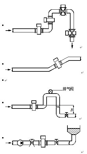
Liquid flow meter installation method
It should be installed at the lower part of the horizontal pipeline and at the vertical upward part, and avoid being installed at the highest point of the pipeline and at the vertical downward part.
7. Grounding requirements
The grounding of the electromagnetic flowmeter is very important. If the grounding is not good, it cannot operate normally. The sensor part should have a good separate grounding wire (copper core cross-sectional area is 1.6mm2) and the grounding resistance is <10Ω.
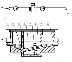
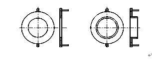
Grounding Ring
If the pipe connected to the sensor is insulating, a grounding ring is required. Its material should be the same as that of the electrode. If the measured medium is abrasive, a grounding ring with a neck should be selected.
Grounding method

8. Change the direction of the converter box
The converter box can be turned in four different directions as needed.
Changing the orientation of the converter box of the integrated flow meter
①Remove the four hexagonal screws that secure the converter box.
②Turn the converter box to the desired direction, paying attention to the internal connection wires while rotating.
③Re-secure the converter box.
Change of the junction box direction of the split flowmeter
①Remove the 4 hexagonal screws that secure the junction box.
②Turn the junction box to the desired direction, paying attention to the internal connection wires when rotating.
③Re-secure the junction box.